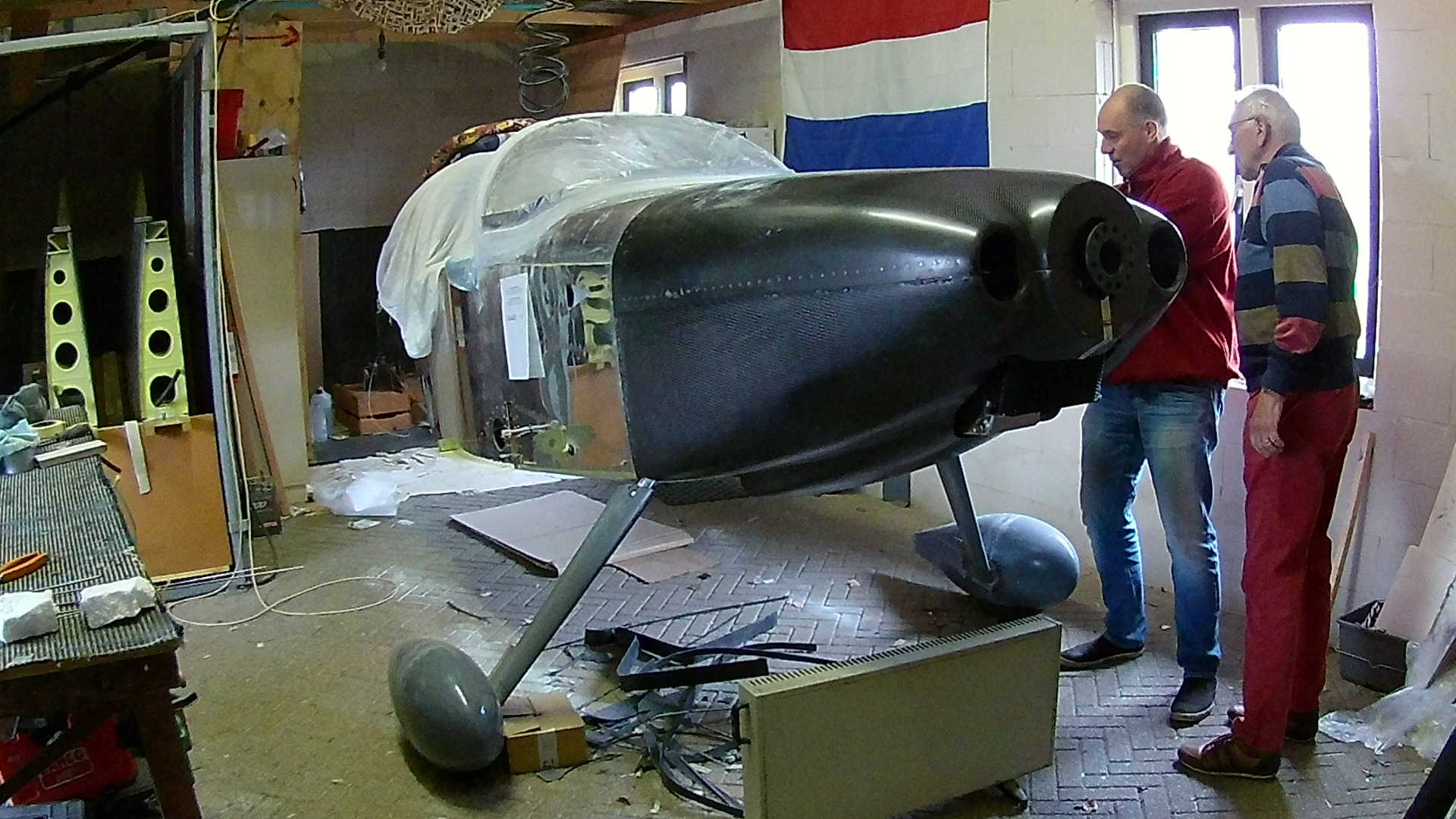
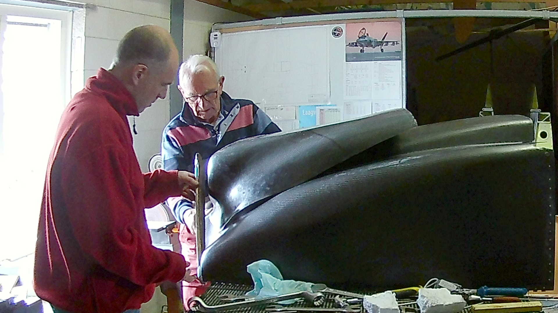
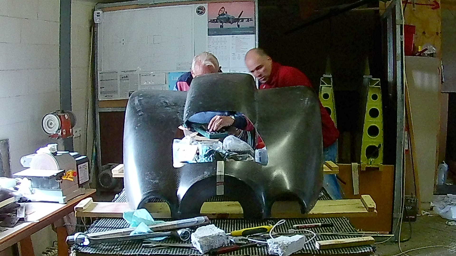
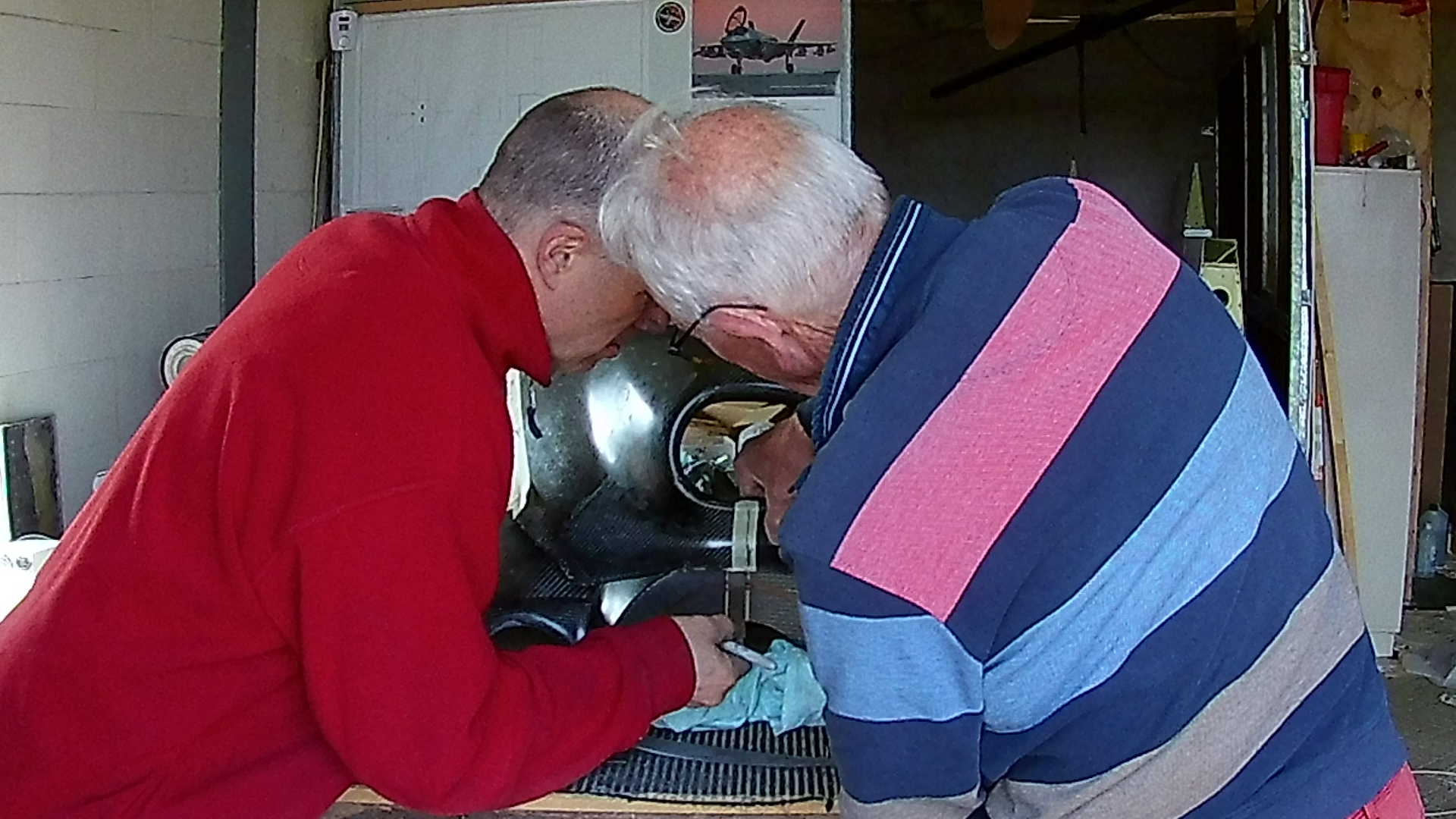
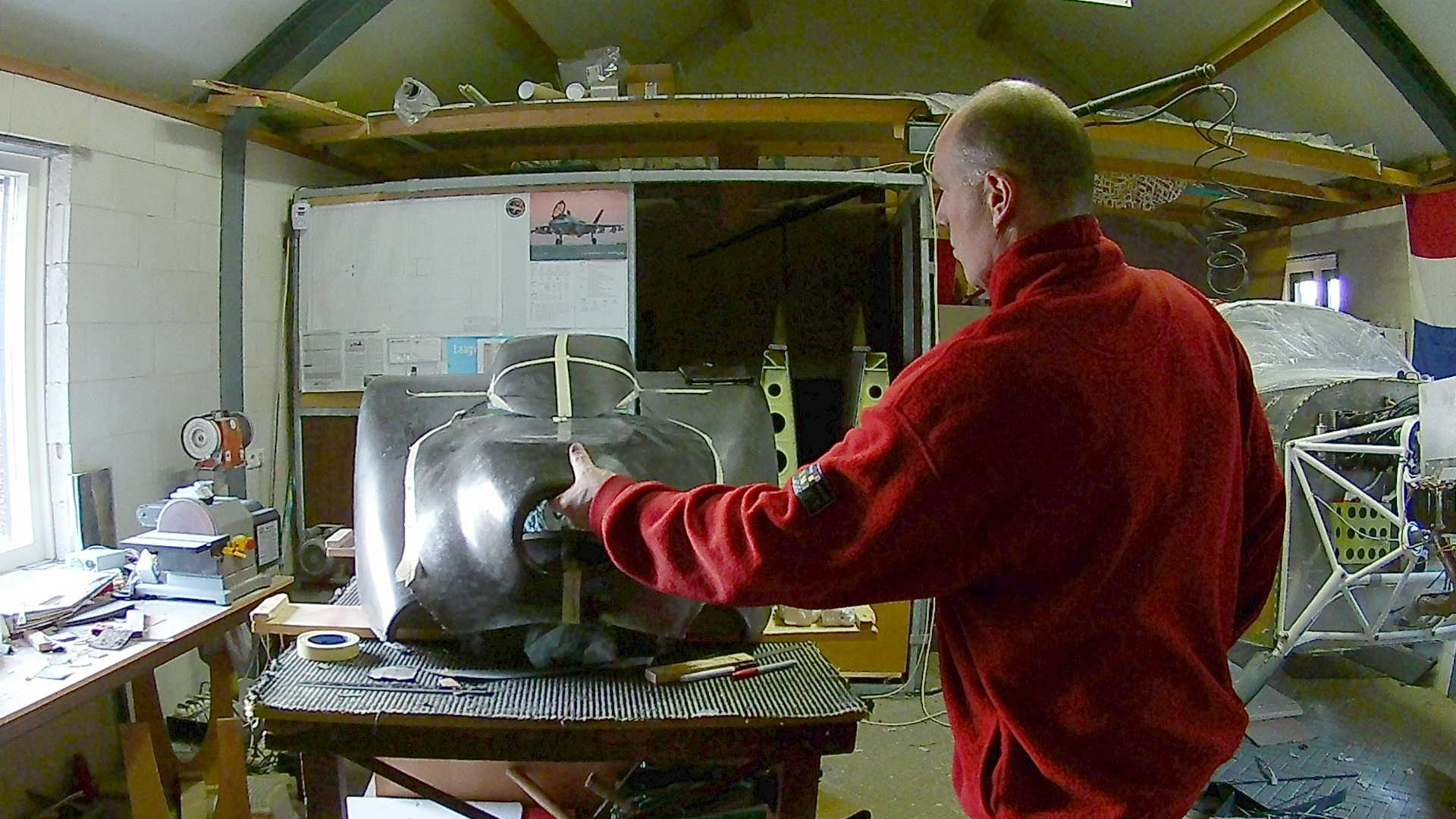
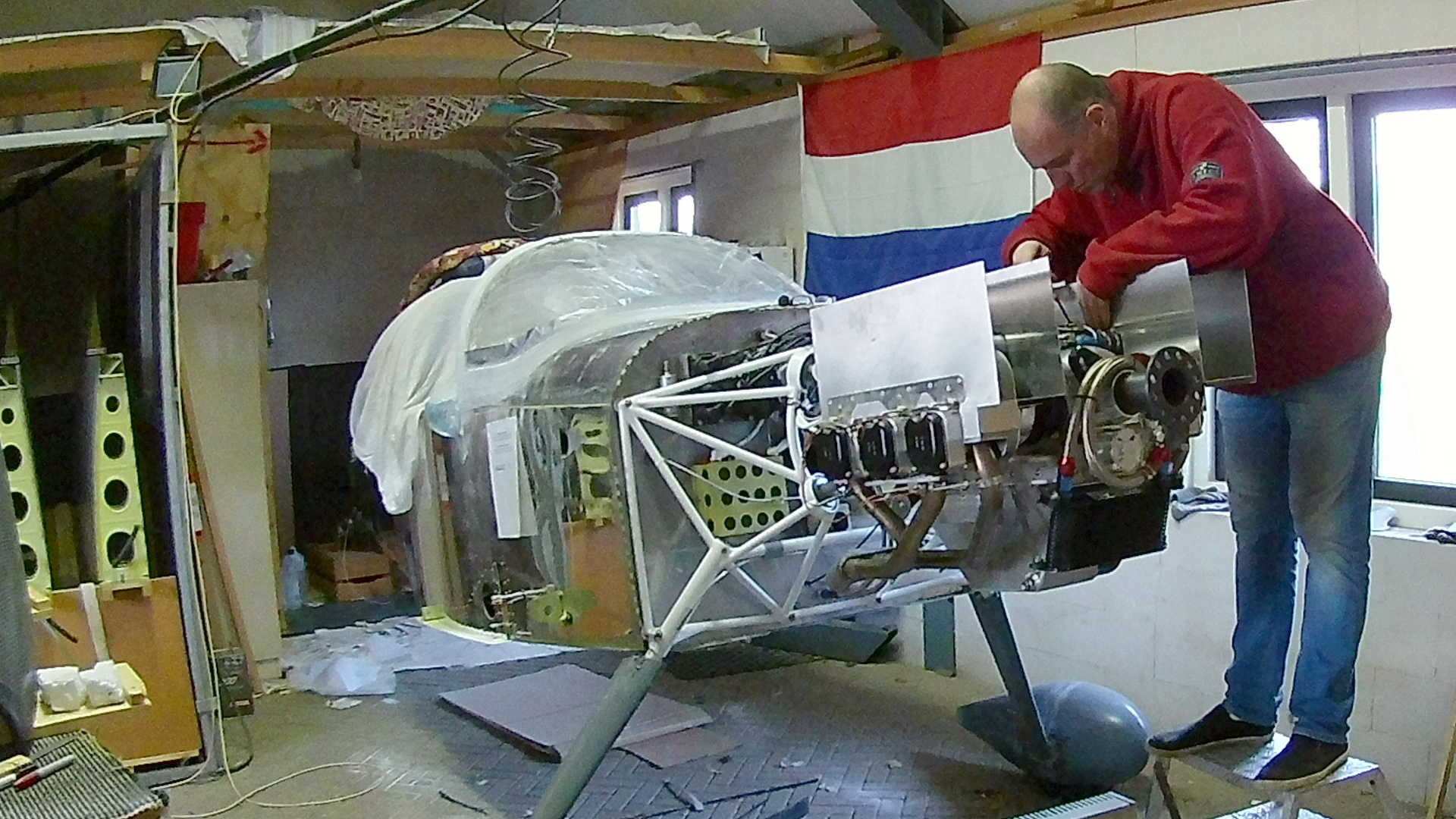
The Top and Bottom Cowl fict very tightly and you can see the hole we made in the bottom Cowl to make room for the Oil Cooler and the Oil Sump.
There is an extra Cowl part delivered for the Air intake of the Oil Cooler. However it took some time before I figured out how to cut the Air Intake and the Bottom Cowl to make it fit. And of course I made a noob mistake working with carbon.
The ULPower engine is delivered with the Oil filter screwed into the engine. The installation kit also holds an Oil thermostat, that opens the flow to the Oil Cooler (if necessary). So first task is to remove the Oil Filter and install the thermostat.
The thermostat has two hose connectors, just as the Oil Cooler and the goal is to connect those with the hoses included. Since setups may vary, you have cut the hose and clamp the connectors to the hose yourself.
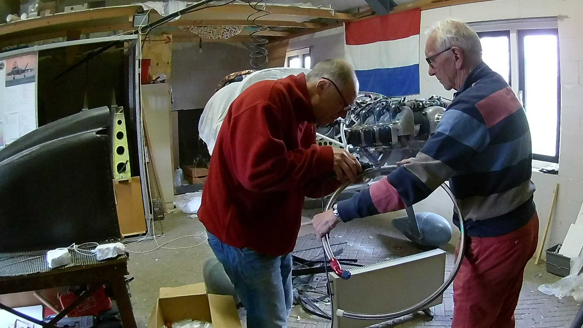
The Oil hoses have a steel braided sleeve and I tried the hand saw, but my results were not suitable for getting the connectors installed after sawing. Here I use the Dremel and I have the hose taped with Duct-tape on both sides to prevent the sleeve from ‘unwinding’.
The connector consists of two parts, the outside nut and the inside connector. You have to push the hose in the Nut and then screw in the connector. After several tries I found that the best way is to:
- tape the hose end before cutting
- gently insert the hose end in the nut (with all the steel threads in the nut)
- push the nut with the hose against the workbench
- remove the tape
- twist the nut with a wrench to make the hose slide into the nut
For inserting the connector in the nut, apply some oil or grease, this makes it way easier to screw the connector in the nut.
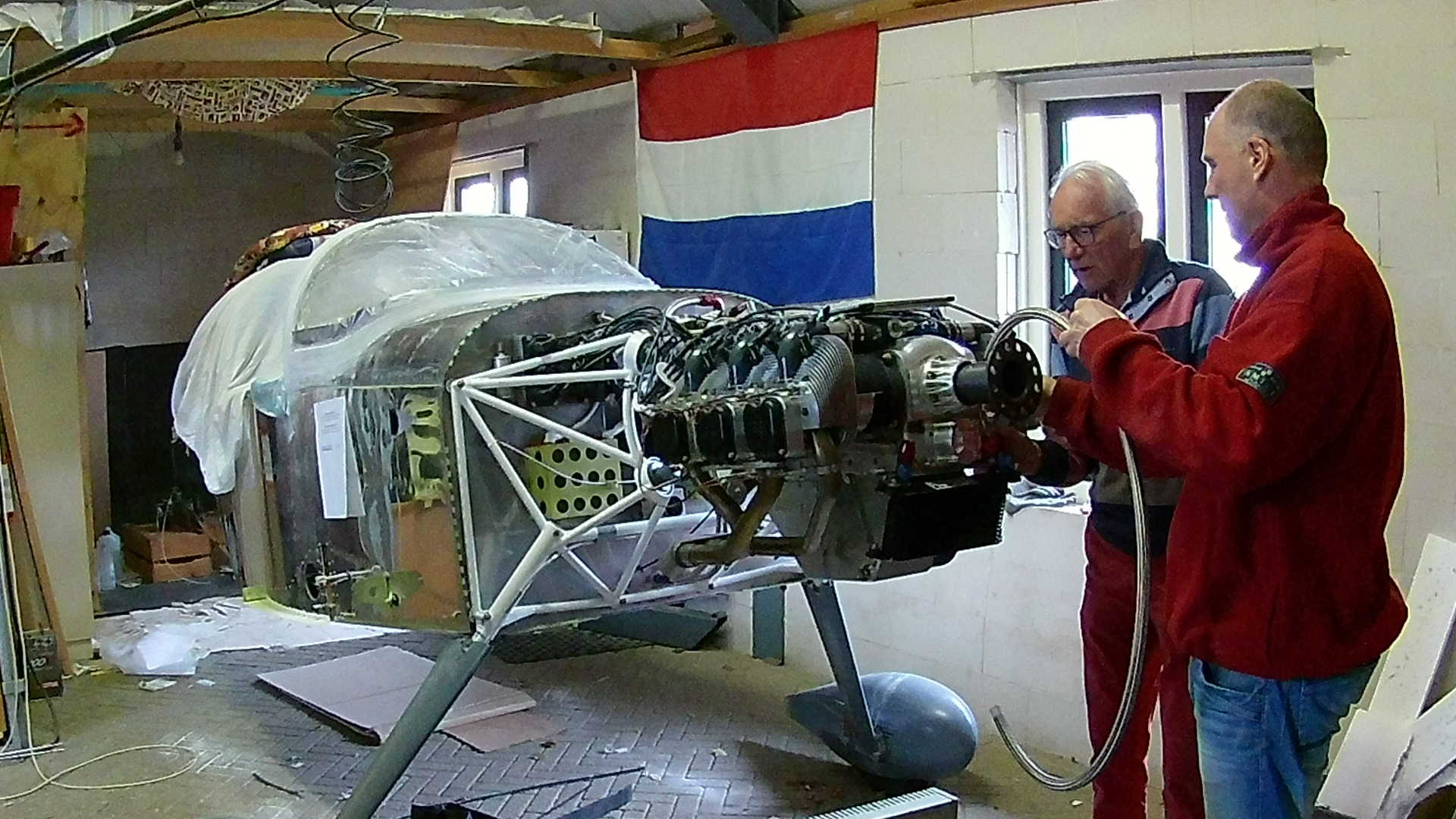
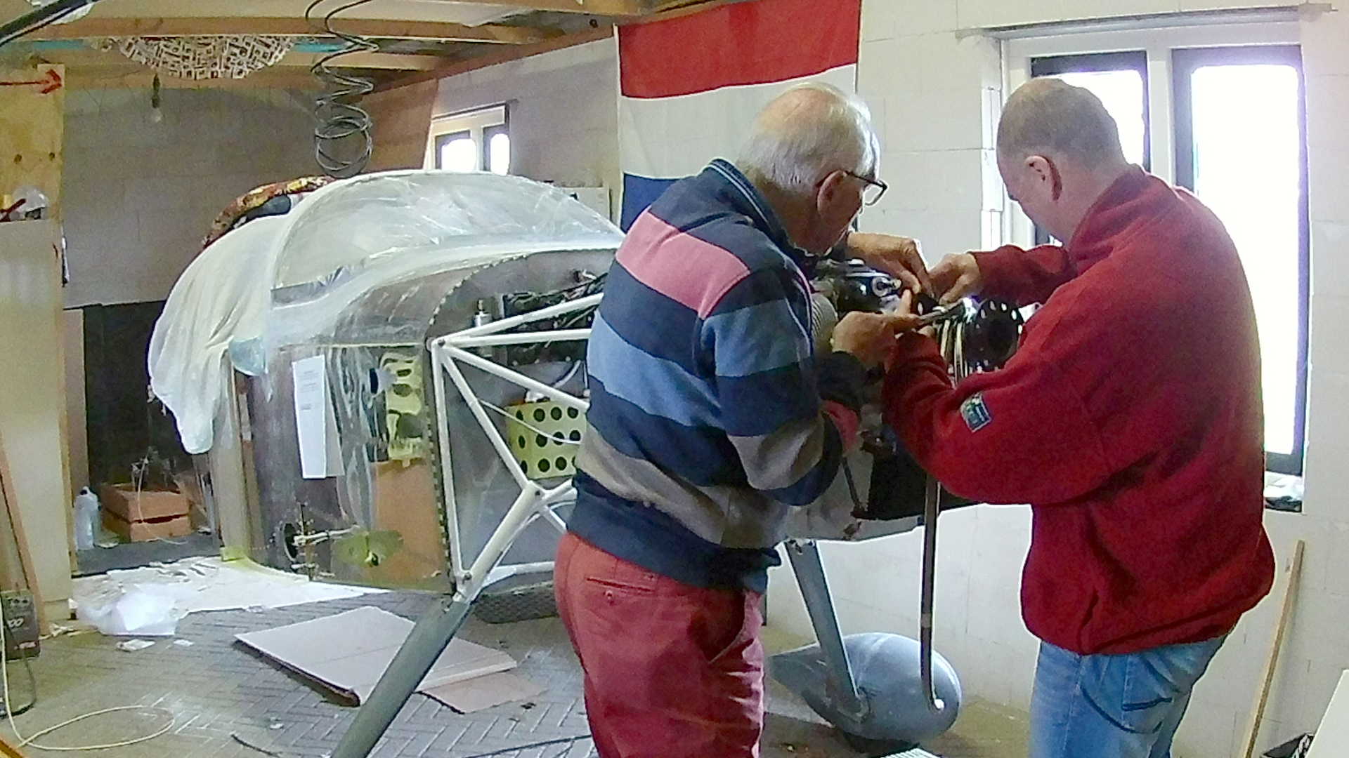
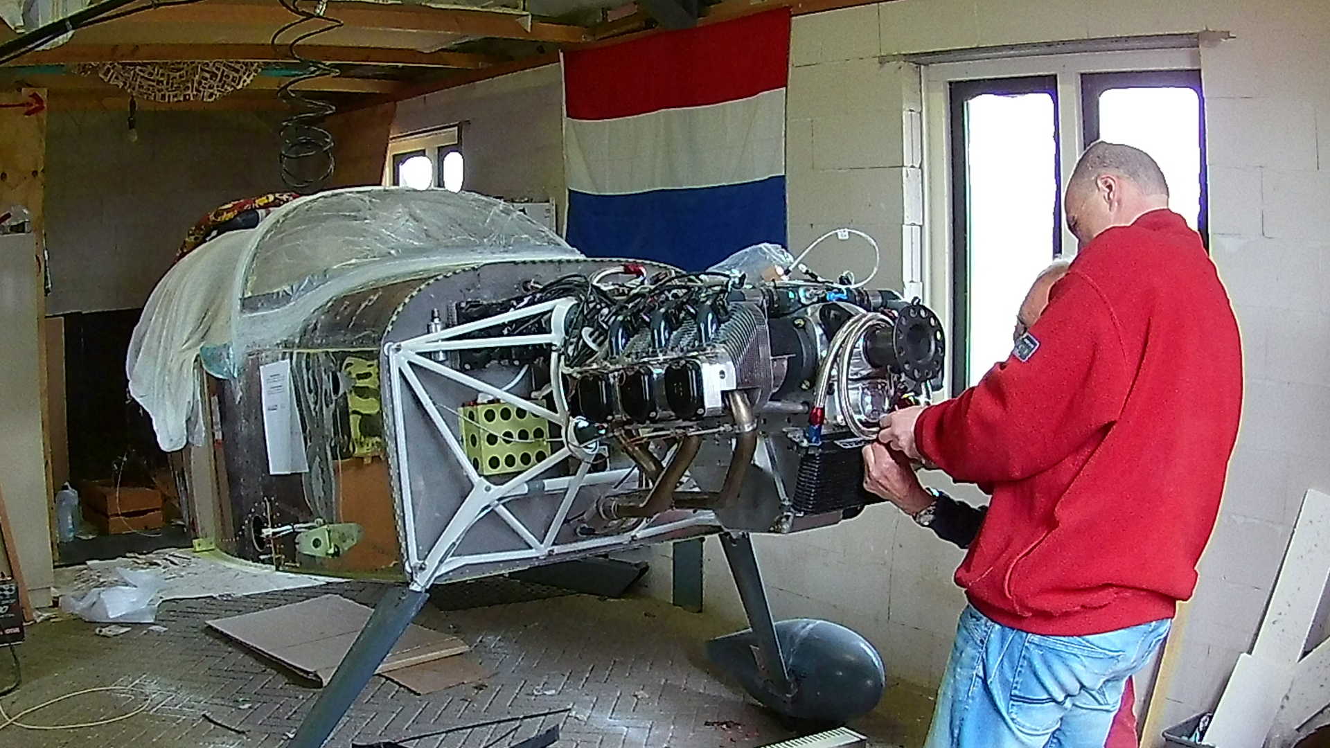
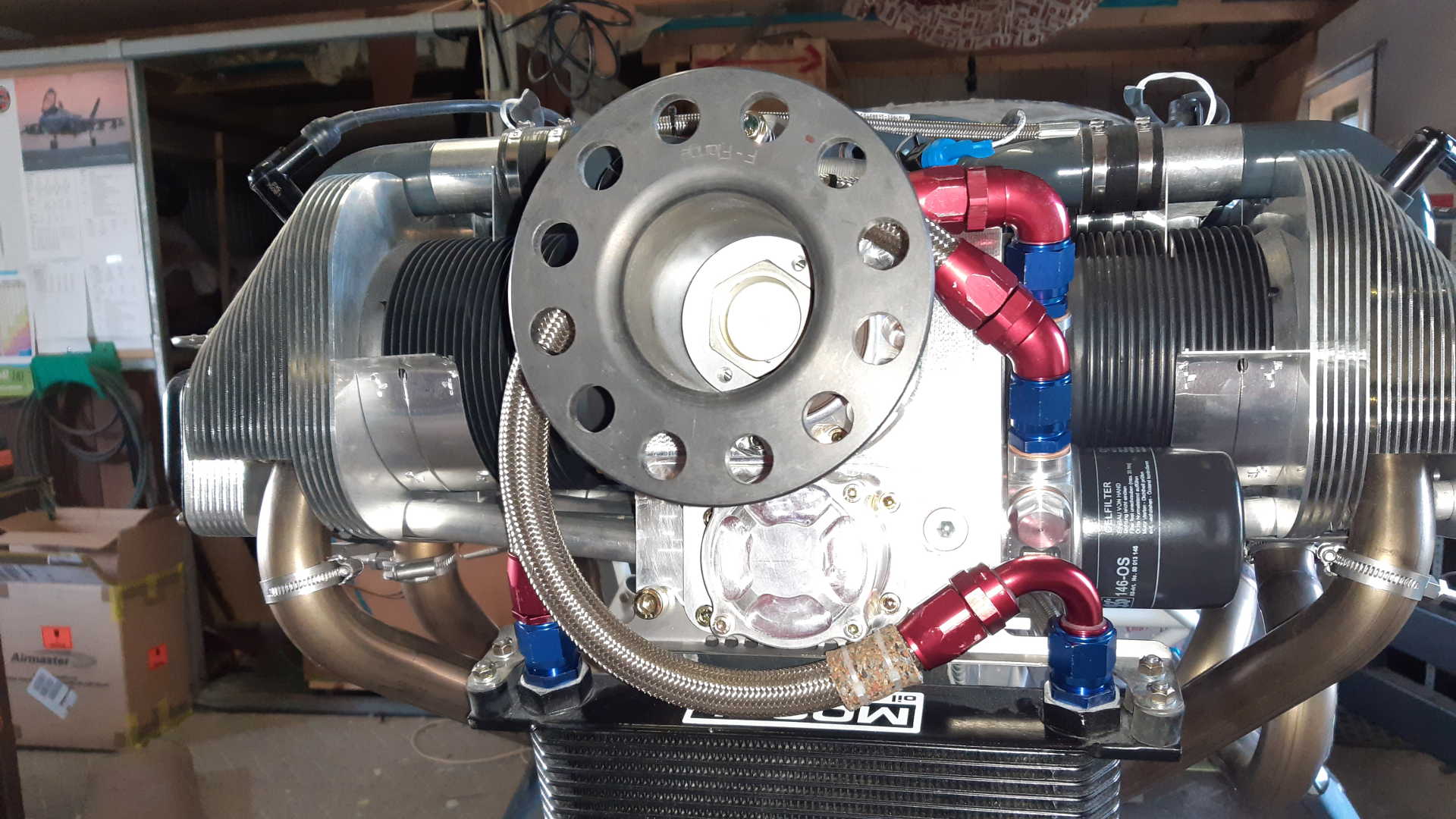
According to the installation guide of ULPower, the hoses should be routed ‘around’ the propeller flange. I don’t see why I can’t directly connect them, but it’s probably a space issue. We have to be careful though, the hoses are routed very near to the arm with the electronic connections of the propeller.
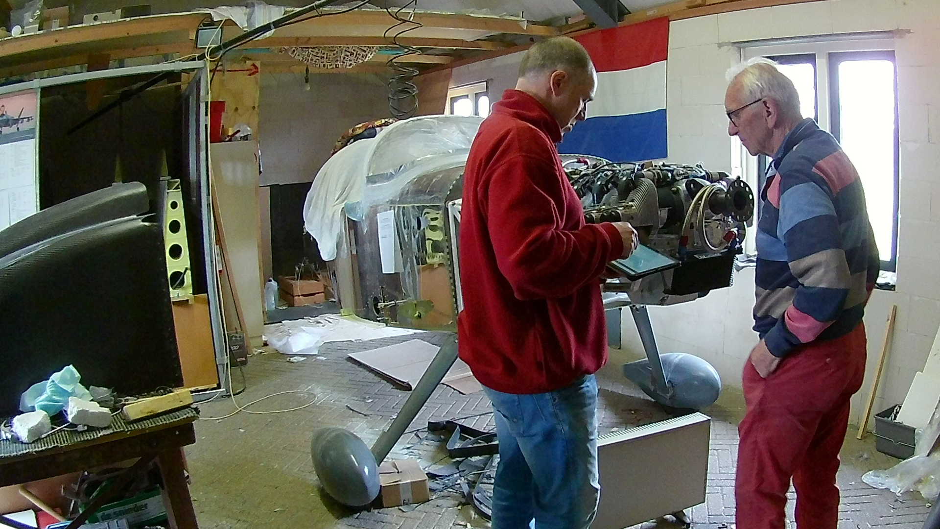
I’m checking the (interactive) installation manual of ULPower, which is exceptionally well structured. I’m wandering what is worse, greasy fingers on a paper manual or an a tablet.
Making the last connection to the Oil Cooler and adding some protective rubber to prevent ‘chafing’ the hose.
Here’s the result. You can see the thermostat between the engine and the oil filter.
Next is the Air Intake for the Oil Cooler. As you can see the mold it came of, allows for many variations. At this point in time I’m still clueless on how to cut these parts.
At least it should not stick ‘over’ the nose of the Cowl. Also the forward top side fits pretty good on the bottom cowl.
A lot of trimming to do, so many opportunities to screw things up.
Here is the first ‘rough’ cut in the Bottom Cowl, which looks horrible and considering the costs of the Cowl made me shiver.
But I finally figured out that I need to cut a wedge type of hole into the Cowl to slide the Air Intake in. Note the wooden beam in the back, clamped to the cowl to keep the shape steady.
Now we have to center the parts and drill holes for cleco’s.
The fit is getting better and better and now I can use sand paper for the last edges. However this is also the point where I make a mistake. I did all the fitting while the Cowl rests on the workbench. Turns out it slightly deforms due to gravity. After gluing the parts together with resin, it didn’t fit the fuselage anymore. So I had to cut again and do it all over.
While the resin and carbon are drying, I work on the Air Boxes that guide the cooling air around the engine. Making these two fit the Cowl is a whole other story.
Time: 7 Hours, Rivets: 0/0 (2021-03-31)
Time: 8 Hours, Rivets: 0/0 (2021-04-04)
Time: 4 Hours, Rivets: 0/0 (2021-04-07)
Time: 6 Hours, Rivets: 0/0 (2021-04-14)
Time: 5 Hours, Rivets: 25/0 (2021-04-17)
Time: 5 Hours, Rivets: 0/0 (2021-04-18)
Time: 6 Hours, Rivets: 0/0 (2021-04-20)
