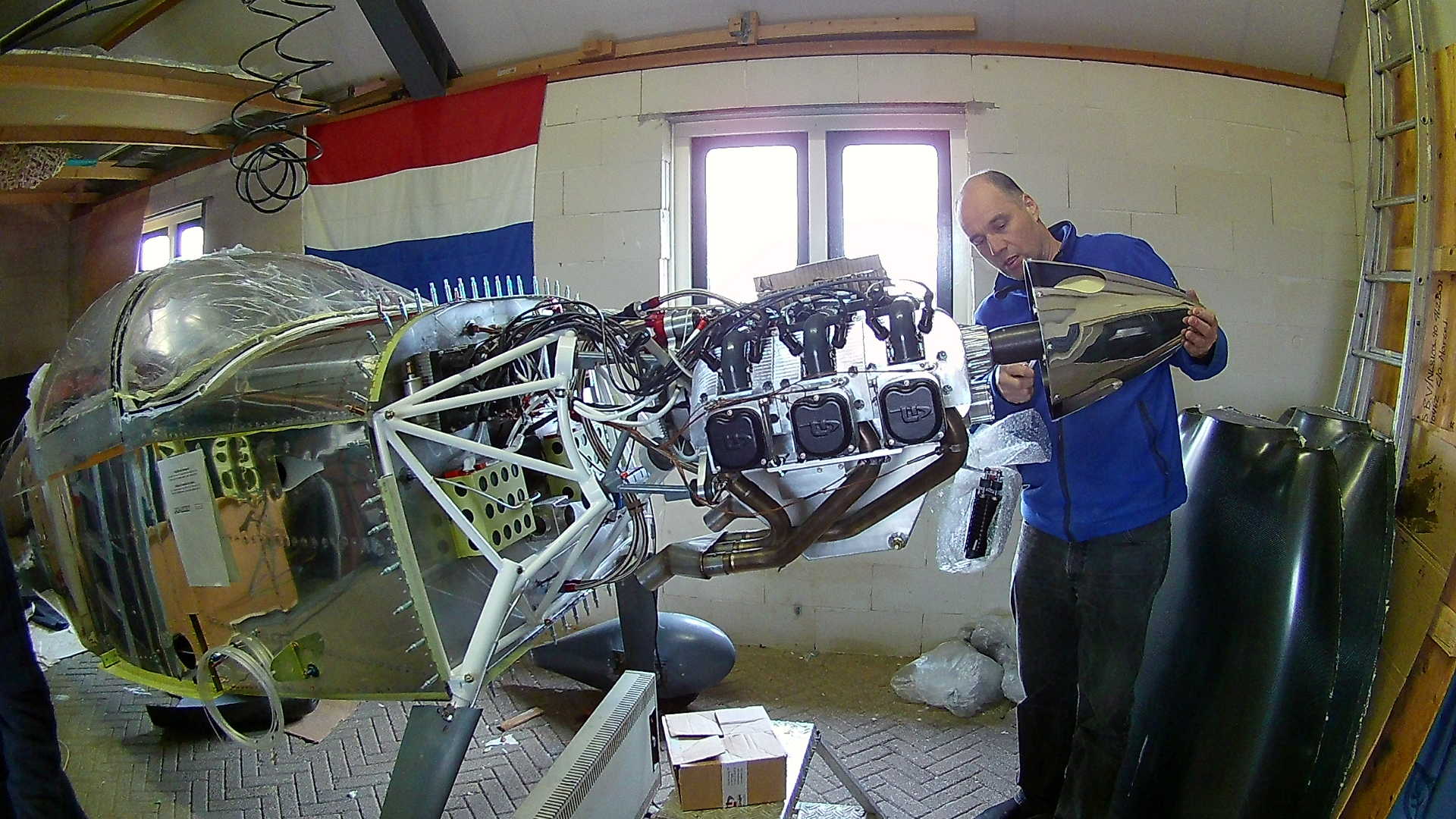
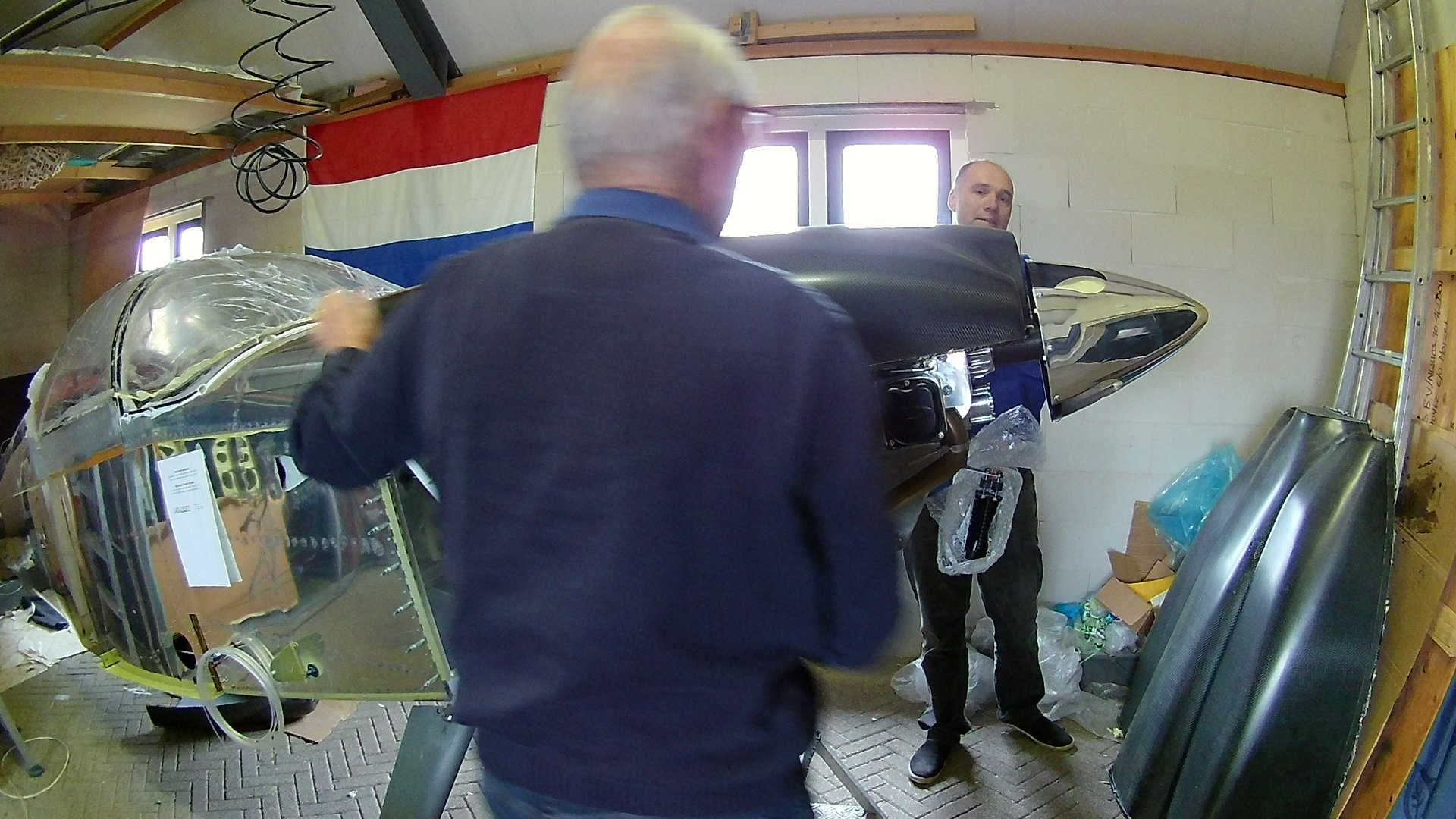
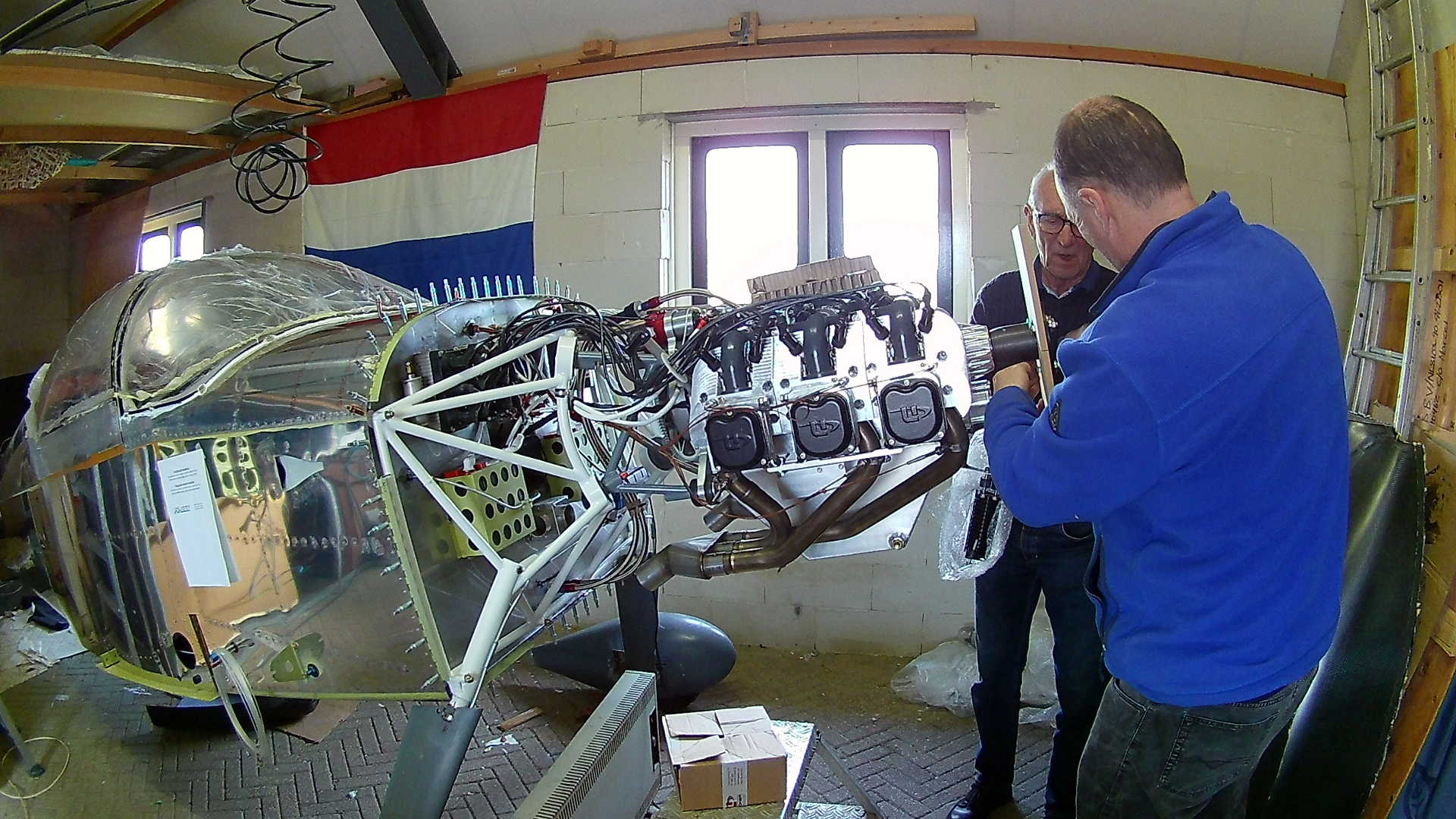
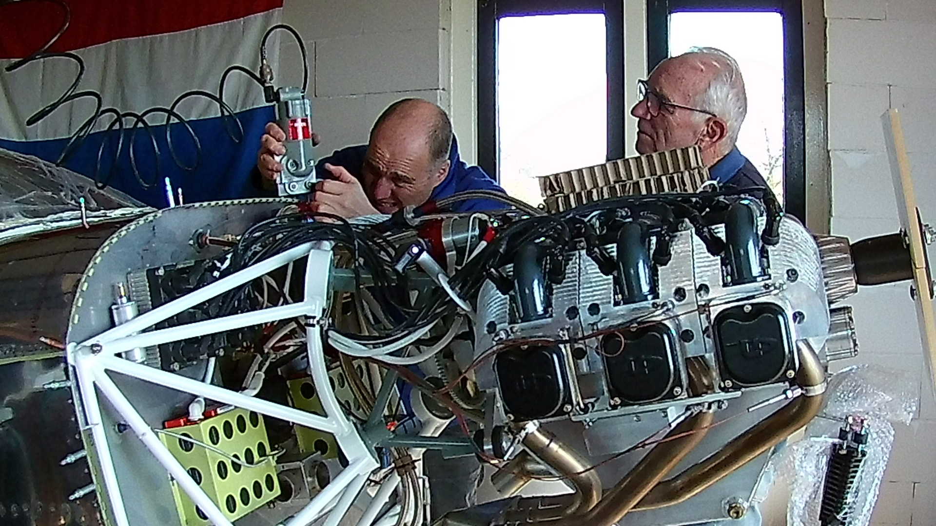
Before starting on working on the Cowl, I first need to install the Spinner, in order to determine the length of the Cowl.
I want to have a close fit between the spinner and the cowl. However I found out later, that I was missing a part in the Engine package, which is the Reducer Flange.
This screwed up my tight fit as the thickness of the Reducer Flange is 3 mm, so the gap between the Cowl and Spinner is now 3 mm larger than I planned. Not a big problem, but still something I don’t like.
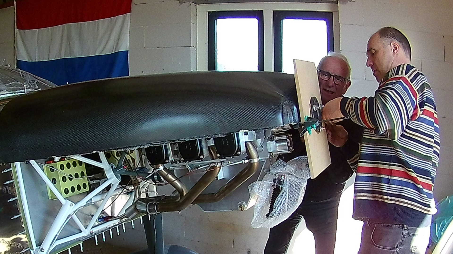
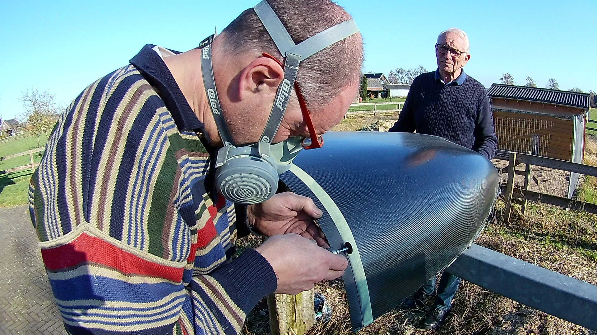
To prevent the spinner from being scratched, I only use it to measure and create a MDF template that I can use to attache the Cowl for trimming. Fortunately the spinner was transported to me from New Zealand on a ‘plate’ that can be transformed to a template.
Here you can see the template up close. On the Van’s RV models, the cowl are not screwed together and to the fuselage, but they are attached with piano-hinges, to create an ‘invisible’ connection. The piano-hinges are riveted together with the firewall to the fuselage.
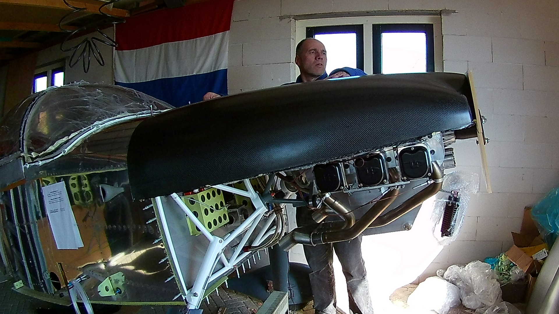
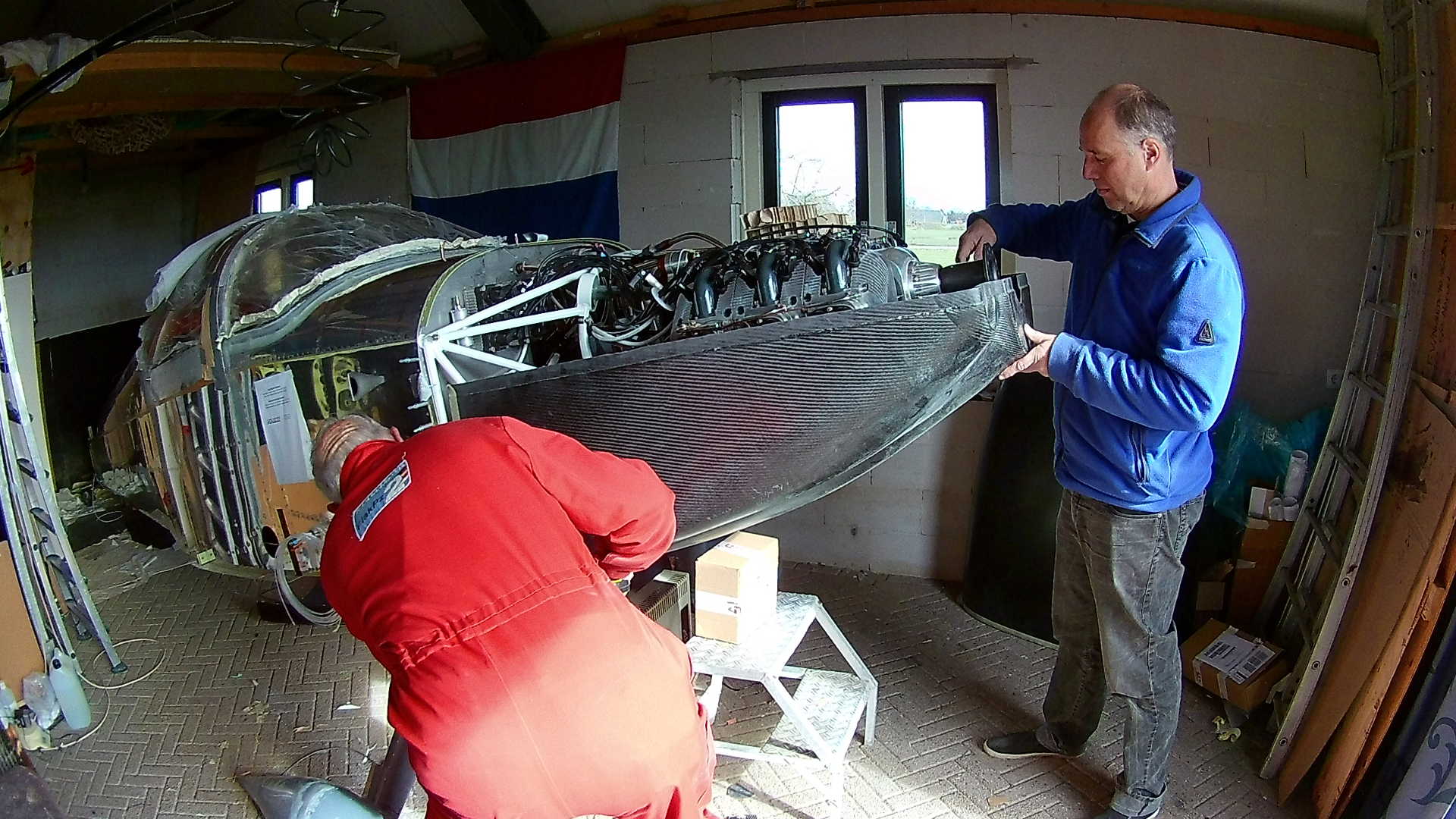
Now I can shift the Top Cowl all the way forward against the template. And you can see the cowl sticks a few inches over the firewall. Also there is no hole in the front of the cowl, hence the forward part is still too high.
I’m cutting the forward part of the cowl to make a ‘hole’ where the crank-shaft flange ca stick to. Turns out the hole must be much bigger, but with cutting, I’m always conservative. Especially with an expensive part as the Cowl, you can’t afford a mistake.
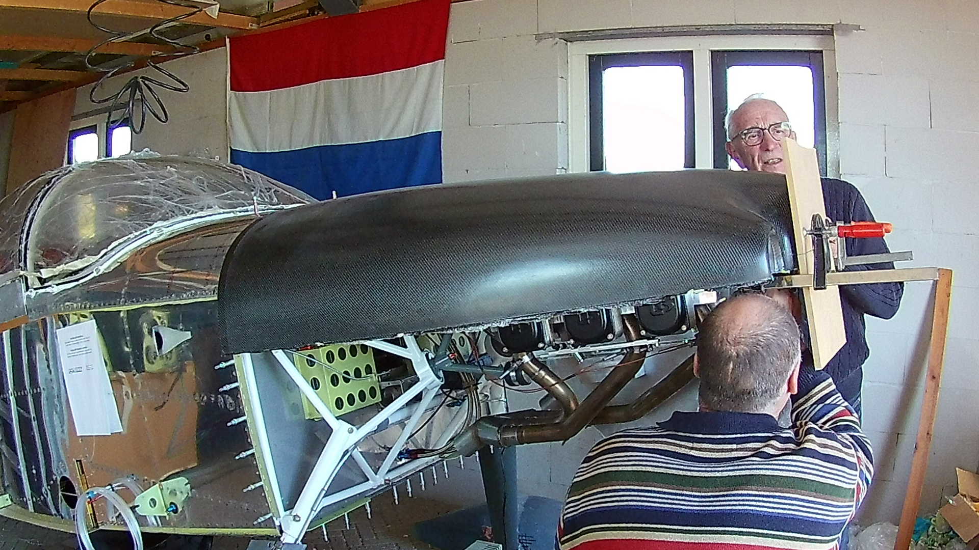
Now the front part of the Cowl can ‘sink’ over the axle to the correct position. We fasten the cowl to the template and fix it with clamps.
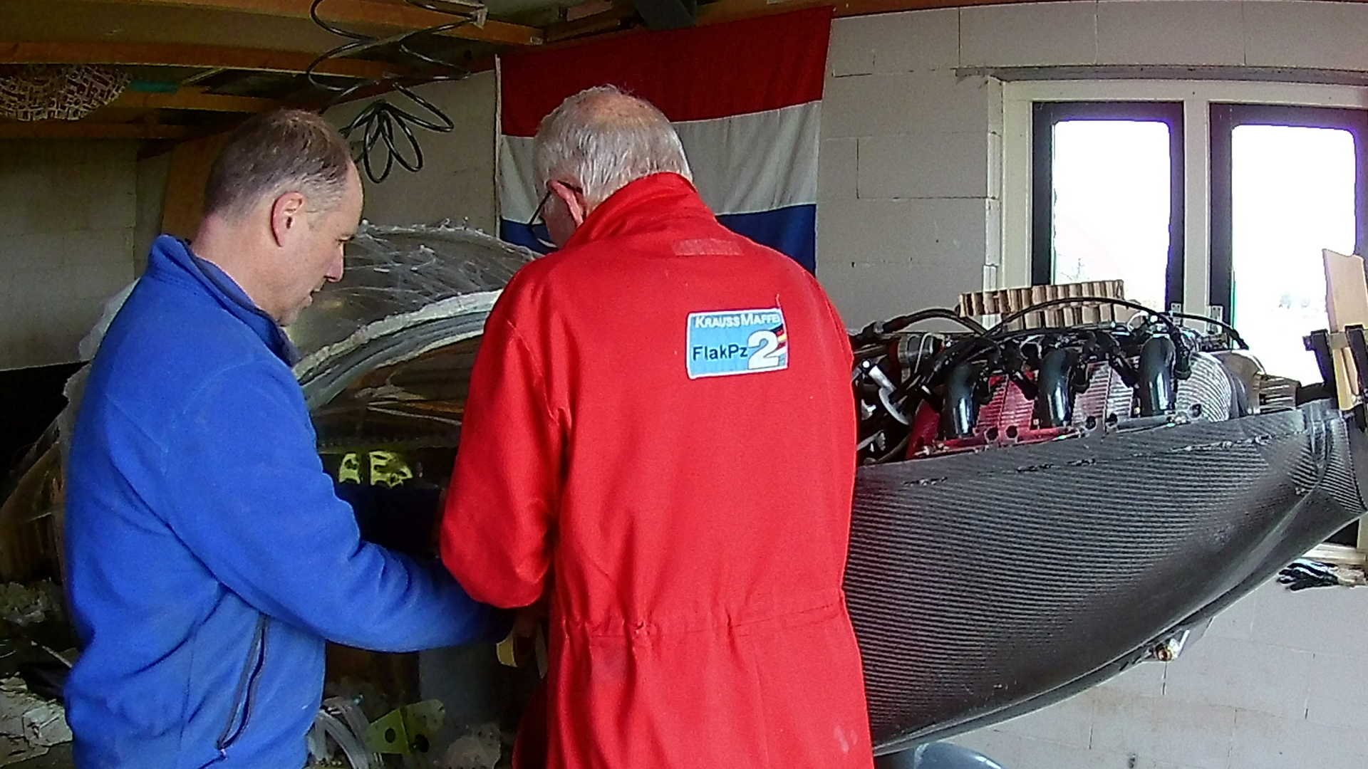
We trim the cowl in two stages. First we trim it to approximately one inch from the firewall. This is still ‘save’, but gives us the opportunity to mark it for final trimming.
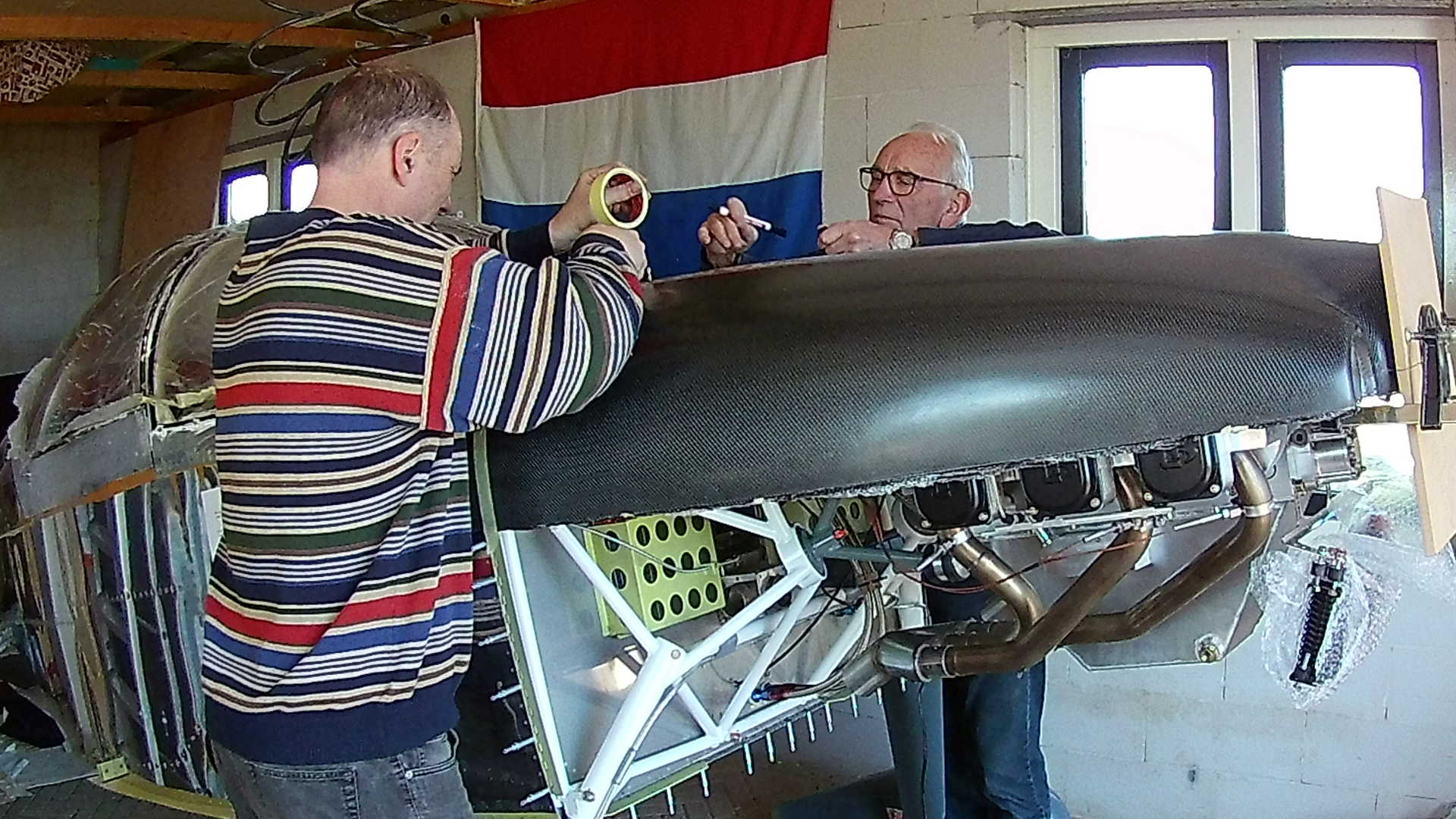
We mark the forward fuselage skin exactly 2 inches from the front. This way we can attach the cowl and still see the markings.
Now we mark the same 2 inch on the cowl and ‘in theory’ that would make it flush with the fuselage. Again I keep a millimetre margin on the save side.
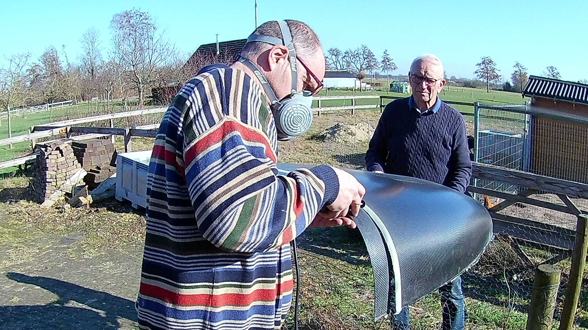
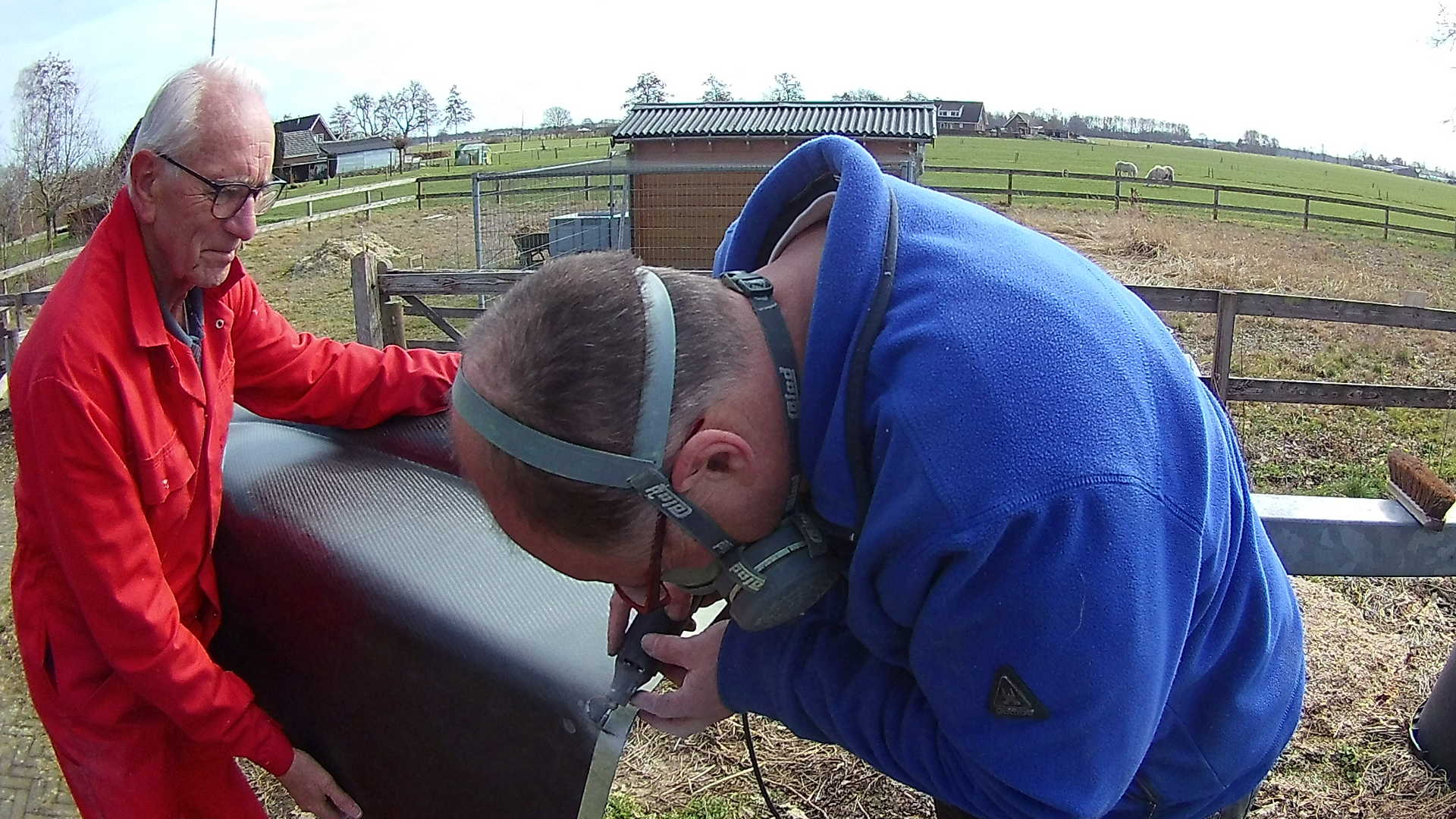
Turns out that carbon is hard on the Dremel disks and they wear really fast. But using sandpaper for the last inch works great. You have to be careful, because the sandpaper cuts into the carbon.
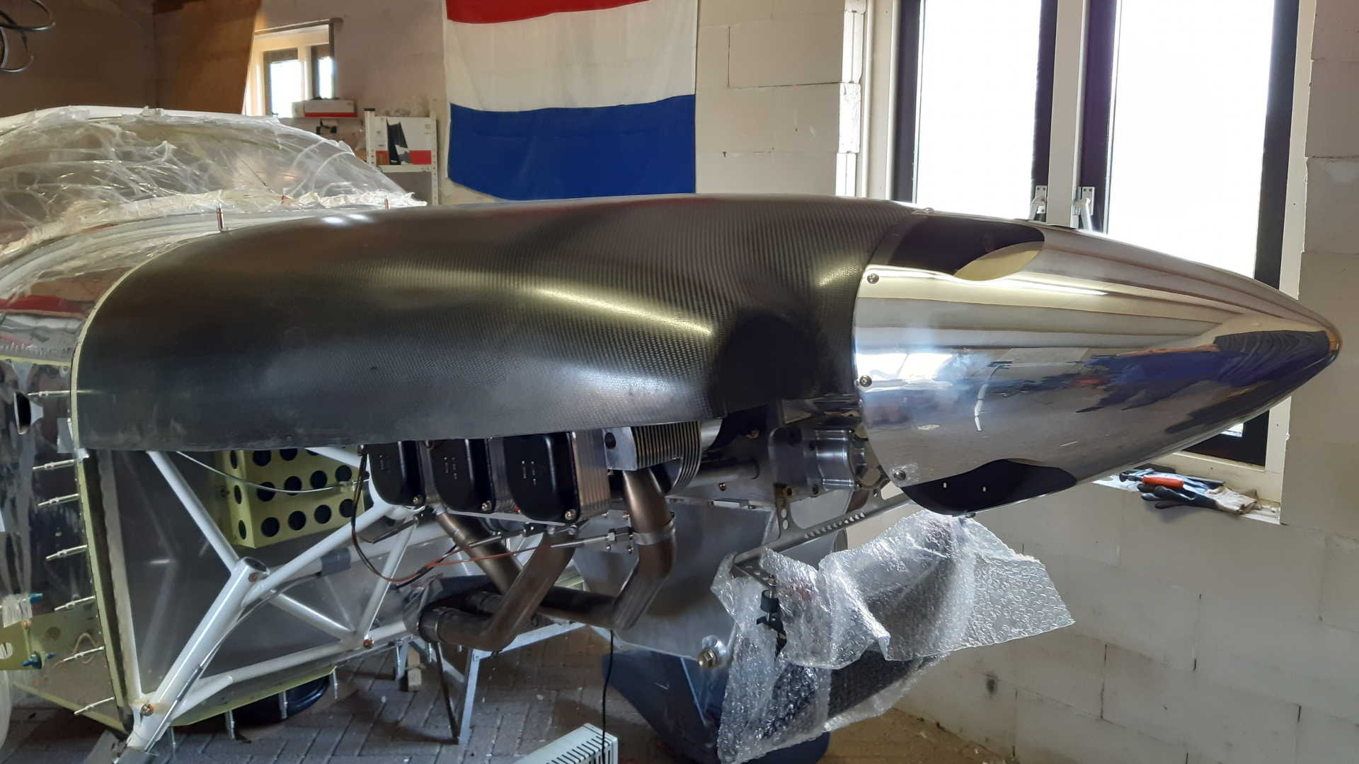
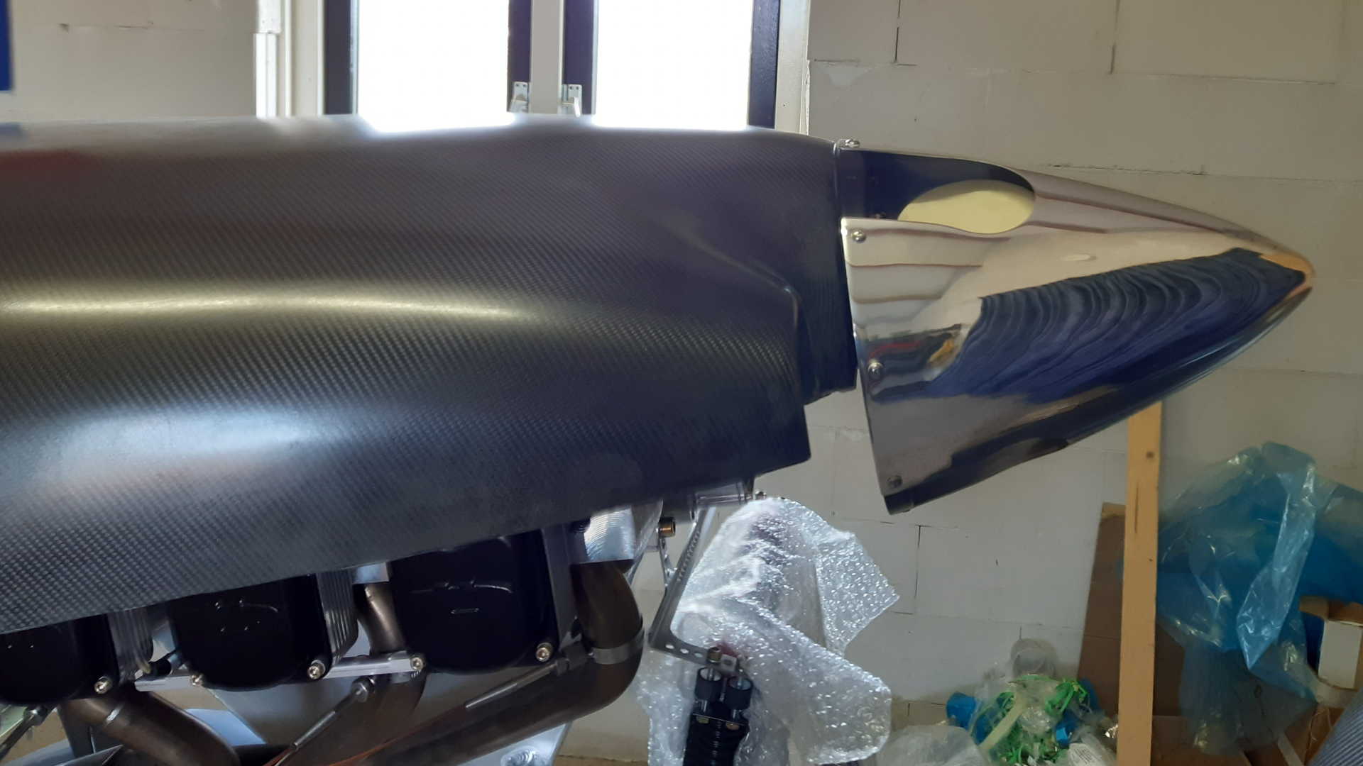
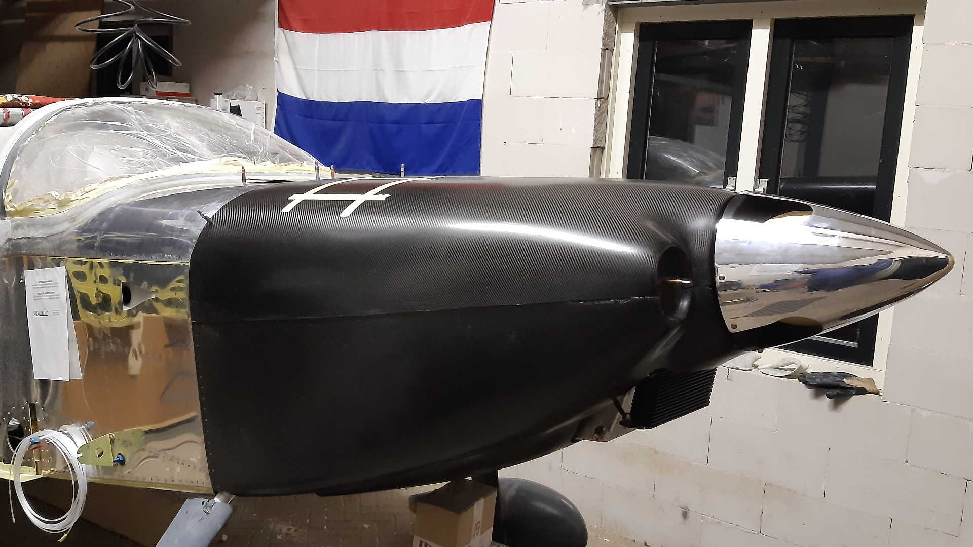
With the cowl fixed to the piano-hinges, I installed the spinner and the distance between the spinner and cowl is a tight fit.
I’m really proud on the result. Too bad I was missing a part, so this tight fit is not here to stay.
We use the same strategy with the bottom cowl. However we can’t fit it, because the sump is in the way. I have to cut a hole in the bottom of the cowl so we can fit it.
Also the gear legs ‘stick’ out forward of the firewall. I have to cut holes in the bottom edges to fit around the gear legs.
These don’t have to be very precise, there are Intersection Fairings that cover the area between the gear leg fairing and the bottom cowl.
Here you can see we made a cutout for the sump in the bottom. This hole needs to be enlarged and covered with the air-duct for the oil cooler.
Here is the result with both the Cowl and the Spinner (including the extra Flange). Also the Sump and oil cooler are sticking out and I’ve marked the oil door with tape.
Time: 7 Hours, Rivets: 0/0 (2021-03-06)
Time: 6 Hours, Rivets: 0/0 (2021-03-10)
Time: 7 Hours, Rivets: 40/0 (2021-03-14)
Time: 6 Hours, Rivets: 30/0 (2021-03-17)
Time: 7 Hours, Rivets: 12/0 (2021-03-21)
Time: 5 Hours, Rivets: 41/6 (2021-03-24)
Time: 7 Hours, Rivets: 0/0 (2021-03-28)
